
JGI Seed Corn Funding Project Blog 2022-2023: Dr Wenzhi Zhou and Prof. Xibo Yuan
The power electronics industry is currently experiencing significant changes due to the emergence of ultra-fast transistors made from wide bandgap (WBG) materials, which are replacing silicon transistors. These new transistors have a switching speed that is 10 times faster, resulting in a 70% reduction in energy loss in converters and enabling motor drive systems to be reduced to less than half their previous size. However, the short voltage rise times (<20ns) and high frequencies (up to MHz) of WBG converters pose new challenges for the insulation of motor drive systems, leading to a drastic decrease in their lifespan.
PD is a well-established diagnostic indicator for assessing the deterioration of electric motor insulation in power converter-fed motor drive systems. It allows for the estimation of service requirements or the prediction of imminent failures. However, the adoption of WBG converters introduces new complexities that can impact the accuracy of PD measurements. Factors such as short voltage rise times (less than 20 ns, comparable to the time it takes light to travel 6 meters) and high frequencies (reaching up to MHz) associated with WBG converters pose significant challenges for insulation within motor drive systems, ultimately leading to a reduction in their lifespan.
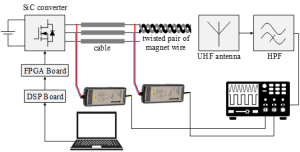
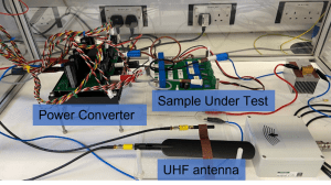
To address these challenges and improve PD detection accuracy, we have undertaken research supported by funding from the Jean Golding Institute (JGI). As part of this endeavour, we have developed a specialized PD detection setup, as illustrated in Figure 1. Figure 1a depicts the schematic representation, while Figure 1b showcases the experimental setup we have established. Through this setup, we have conducted preliminary experiments to examine PD behaviour under different excitations, including two-level and three-level pulse width modulation (PWM) waveforms. An example of the PD signal observed under two-level PWM excitations is shown in Figure 2.
|
(A) |
(B) |
| Fig. 1 Experimental PD setup: (a) schematic and (b) hardware. | |
 |
| Fig. 2. The PD signal under the two-level PWM excitation. |
The JGI funding has also facilitated collaboration with esteemed experts in the field, including Dr. Jin Zheng from the Engineering Mathematics Department and Dr. Wenbo Wang from Dynex Semiconductor. Their expertise and insights will play a crucial role in advancing our research efforts. Furthermore, we plan to leverage state-of-the-art artificial intelligence techniques to analyse the data we have collected. These techniques will enable us to extract meaningful insights and further enhance our understanding of PD in WBG-based motor drive systems.